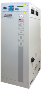
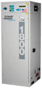
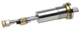
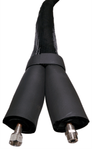
Cryochiller Models
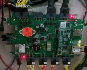
Telemark cryochillers provide efficient closed-loop cryogenic refrigeration for water vapor pumping with cooling capacities from 1200W to 4800W. Telemark cryochillers support state of the art communications and full system integration. The digital control package operates at 24V and contains a battery backup. On-board RS-232, RS-485 and Ethernet communications will meet your remote operation needs and supports complete data-logging. Optional Profibus and EtherCAT interfaces are available. Analog system control is also available. The back-lit on-cabinet LCD screen readouts allow rapid scrolling through all available monitor points. Likewise, all available monitor points can be sent remotely to a deposition controller for automated operation.
Direct competitor to Brooks Polycold®
Registered trademark of Brooks Automation, Inc.
- Fast “Cool Down” for shorter cycle times
- More Efficient Water Vapor Pumping
- Small Footprint
- Fast Defrost
- Comprehensive Digital Control Package with Digital Communication Connectivity
Water Vapor Cryotraps:
- Decrease Pump down Times by 25% to 90%
- Attain Deeper Vacuum
- Improve Deposition Quality
- Eliminate Costly LN2 Usage For Fast Payback
| Model 1200 | Model 1800 | Model 2400 | Model 3000 | Model 3600 | Model 4800 | |
|---|---|---|---|---|---|---|
| Maximum Load (Watts) | 1200 | 1800 | 2400 | 3000 | 3600 | 4800 |
| Theoretical Pumping Speed l/sec | 100000 | 150000 | 200000 | 245000 | 300000 | 400000 |
| Typical Pumping Speed l/sec | 65000 | 100000 | 135000 | 165000 | 200000 | 270000 |
| Ultimate Vacuum | 2 x 10⁻⁸ (torr) mbar | 2 x 10⁻⁸ (torr) mbar | 2 x 10⁻⁸ (torr) mbar | 2 x 10⁻⁸ (torr) mbar | 2 x 10⁻⁸ (torr) mbar | 2 x 10⁻⁸ (torr) mbar |
| Weight | 425 lbs. (193 kg) | 485 lbs. (243 kg) | 485 lbs. (243 kg) | 845 lb. (384 kg) | 930 lb. (412 kg) | 990 lb. (449 kg) |
| Power supply | 380-440VAC 3 ph 50 Hz or 460VAC 3 ph 60 Hz or 200-230VAC 3 ph 50/60 Hz | 380-440VAC 3 ph 50 Hz or 460VAC 3 ph 60 Hz or 200-230VAC 3 ph 50/60 Hz | 380-440VAC 3 ph 50 Hz or 460VAC 3 ph 60 Hz or 200-230VAC 3 ph 50/60 Hz | 380-440VAC 3 ph 50 Hz or 460VAC 3 ph 60 Hz or 200-230VAC 3 ph 50/60 Hz | 380-440VAC 3 ph 50 Hz or 460VAC 3 ph 60 Hz or 200-230VAC 3 ph 50/60 Hz | 380-440VAC 3 ph 50 Hz or 460VAC 3 ph 60 Hz or 200-230VAC 3 ph 50/60 Hz |
| Full load Current Draw @ 60Hz @200-230V | 20 Amps | 30 Amps | 40 Amps | 50 Amps | 60 Amps | 96 Amps |
| Full load Current Draw @ 60Hz @380-440V | 10 Amps | 15 Amps | 20 Amps | 25 Amps | 30 Amps | 48 Amps |
| Start Up Max Current Draw @ 60Hz @200-230V | 30 Amps | 60 Amps | 60 Amps | 60 Amps | 85 Amps | 110 Amps |
| Start Up Max Current Draw @ 60Hz @380-440V | 15 Amps | 30 Amps | 30 Amps | 30 Amps | 45 Amps | 60 Amps |
| Water requirement (Maximum) | 5 lt/min @ 15°C, 10 lt/min @ 25°C, 20 lt/min @ 32°C | 5 lt/min @ 15°C, 10 lt/min @ 25°C, 20 lt/min @ 32°C | 6 lt/min @ 15°C, 12 lt/min @ 25°C, 30 lt/min @ 32°C | 6 lt/min @ 15°C, 12 lt/min @ 25°C, 30 lt/min @ 32°C | 8 lt/min @ 15°C, 16 lt/min @ 25°C, 30 lt/min @ 32°C | 10 lt/min @ 15°C, 18 lt/min @ 25°C, 30 lt/min @ 32°C |
| Water connections | 3/4” NPT female | 3/4” NPT female | 3/4” NPT female | 3/4” NPT female | 3/4” NPT female | 3/4” NPT female |
| Refrigeration Connections | ½” UltraSeal | ½” UltraSeal | ½” UltraSeal | ½” UltraSeal | ½” UltraSeal | ½” UltraSeal |
Selection of Appropriate Model
The model 1200 deals with heat loads up to 1200 watts and can typically trap up to 55,000 l/sec of water vapor, at a variety of vacuum depths. The 1800 deals with heat loads up to 1800 watts and typically traps up to 80,000 l/sec of water vapor at a variety of vacuum depths. The model 2400 handles up to 2400 watts and traps up to 125,000 l/sec, in a typical installation. The 3000 handles heat loads to 30000 watts, and typically traps up to 165,00 l/sec of water vapor. The 3600 can manage a combined heat load of 3600 Watts and typically traps up to 200,000 l/sec.
When determining the optimum vapor trapping capability to significantly improve pump-down times, a preliminary goal should be to achieve at least four times the current water vapor trapping capability of your high vacuum pump.
Selection of the correct model cryotrap depends upon two primary factors: the amount of water vapor that needs to be trapped, and the total heat load the system needs to manage.
Heat load
Total heat load is a combination of: 35 watts/square ft. of cryosurface, 8 Watts per linear ft. of insulated refrigerant line, “latent” heat loads which are extensive at shallow vacuum depth but can be ignored at 10-4 or below, and in-chamber heating of:
| Black Body, Load in W/sq ft | Shielded, Load in W/sq ft | |
|---|---|---|
| 50 deg. C | 55 | 42 |
| 100 deg. C | 100 | 75 |
| 150 deg. C | 167 | 125 |
| 200 deg. C | 262 | 197 |

